This is an old revision of the document!
Table of Contents
My New 30m CW QRP TX is finished
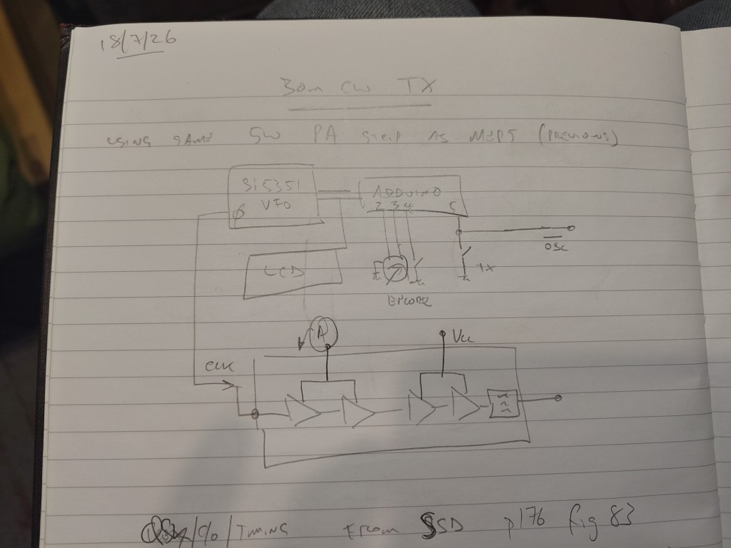
This is re-using the same PA strip as the QRSS MEPT QRSS MEPTI've changed the Arduino code and added a rotary encoder and LCD.
Basic Architecture
I've also built a “QSK” board that handles the antenna changeover relay, TX VFO enable/disable and keying the driver stage of the PA strip.
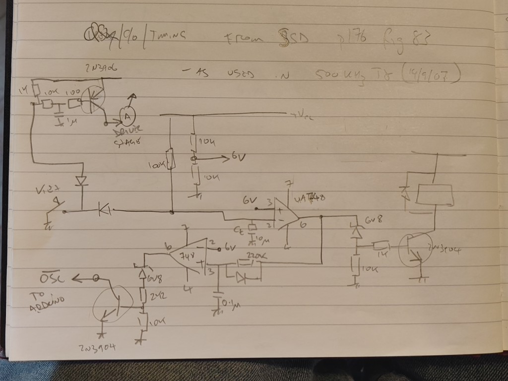
It's still a work in progress….
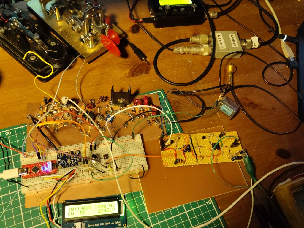
The boards on the bench :
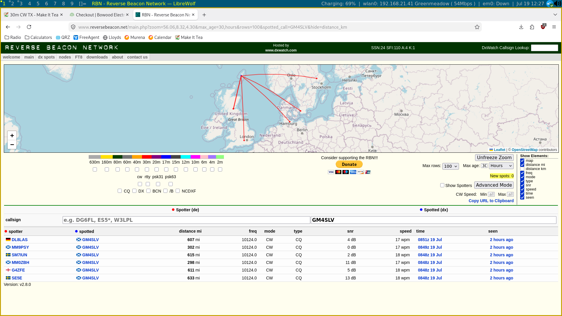
RBN Spots of me calling CQ with 1W - using the antenna c/o QSK board etc.
Final Build
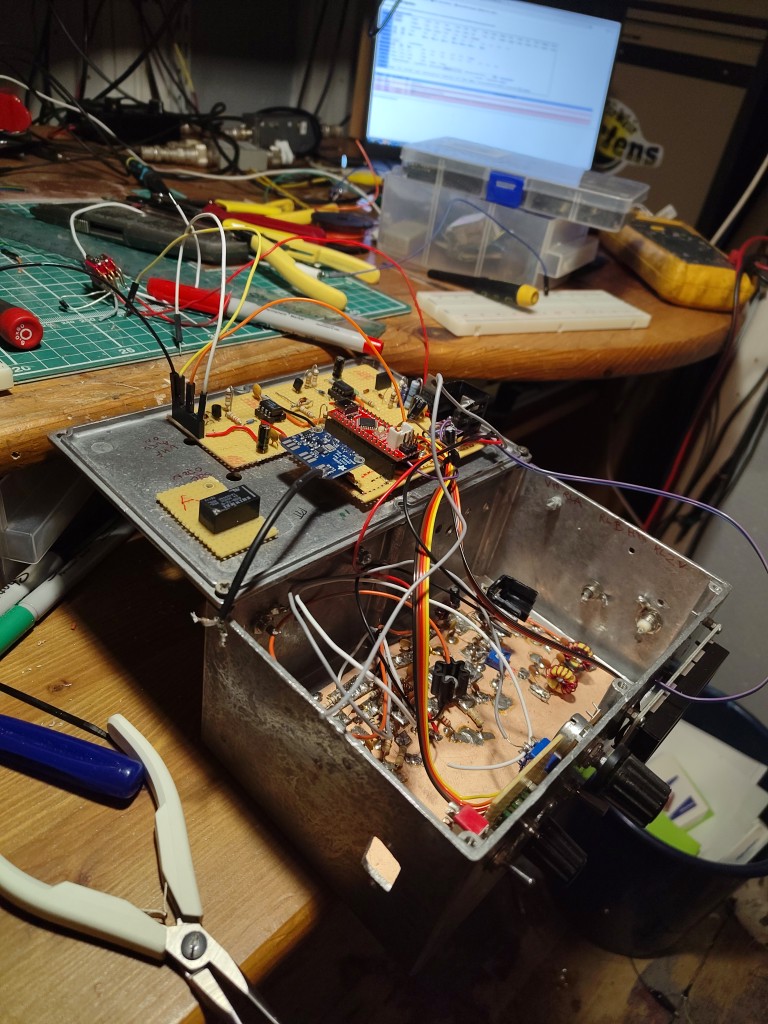
I repurposed an enclosure from a previous project and started cramming everything in.
And here it is, finished and incorporated into the shack
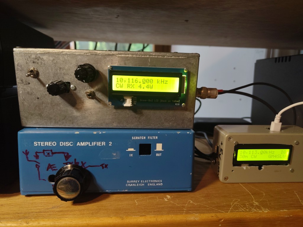
The final feature set:
- Arduino (Seeeduino nano) controlling an SI5351 clock board
- LCD Display
- Frequency
- RX / TX status
- Approximate TX Power setting (calculated from PA supply Voltage measured by the Arduino ADC)
- Semi-QSK
- Internal Antenna C/O relay
- RX Mute line (ground to mute)
- Variable TX Output power via voltage regulator on DC supply to final class-C IRF510 MOSFET
- Output adjustable 0.1W → 5W
Separate TX and RX
I considered making a transceiver by putting the phasing RX 30m Phasing Rx and this TX together in one box, with a single Arduino / SI5351 but I decided to keep them totally separate. This harks back to an earlier time when this was a common way of operating. There is much more versatility from this approach.
Further Information
Page created : 19/07/26 12:20 BST
Page updated : 25/07/26 15:38 BST


