My New 30m CW QRP TX is finished
A new TX is born
This new TX is re-using PA strip I tried in the QRSS MEPT I've changed the Arduino code and added a rotary encoder and LCD.
Basic Architecture
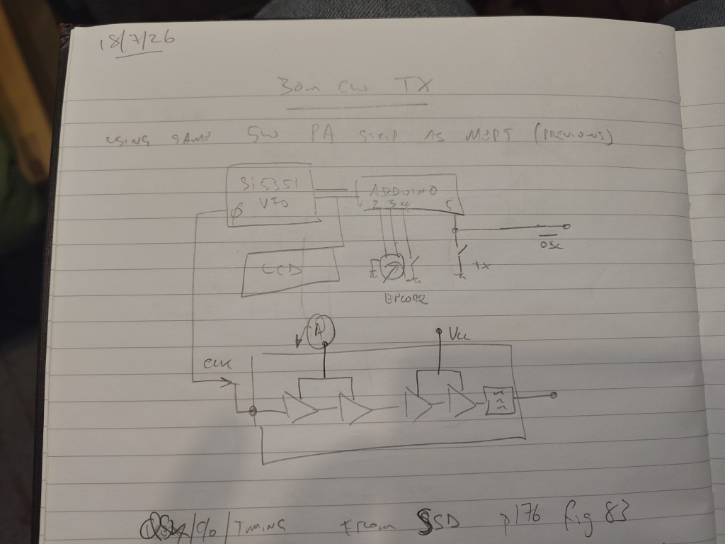
I've also built a "QSK" board that handles the antenna changeover relay, TX VFO enable/disable and keying the driver stage of the PA strip.
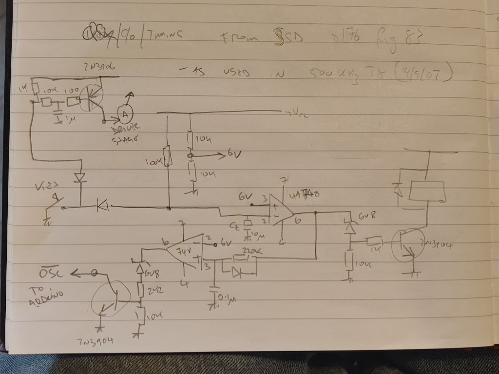
It's still a work in progress....
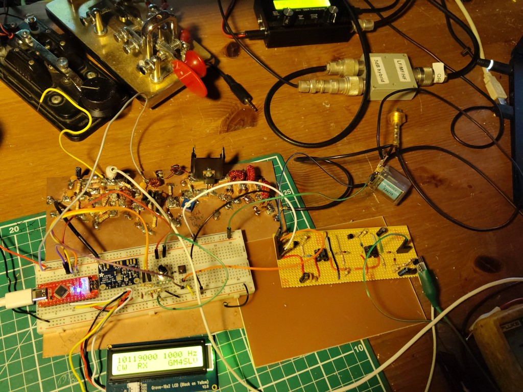
The boards on the bench :
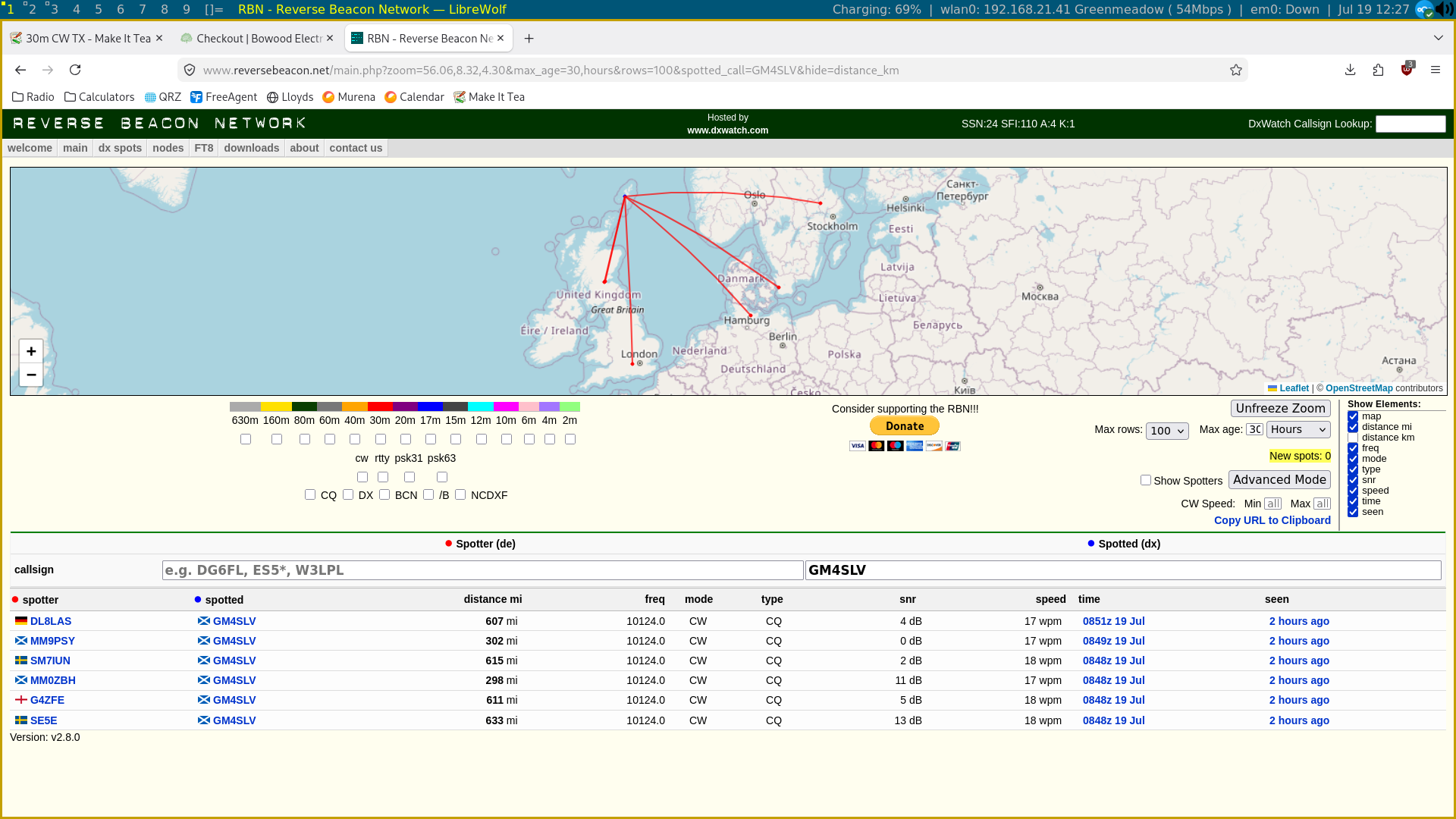
RBN Spots of me calling CQ with 1W - using the antenna c/o QSK board etc.
Final Build
I repurposed an enclosure from a previous project and started cramming everything in.
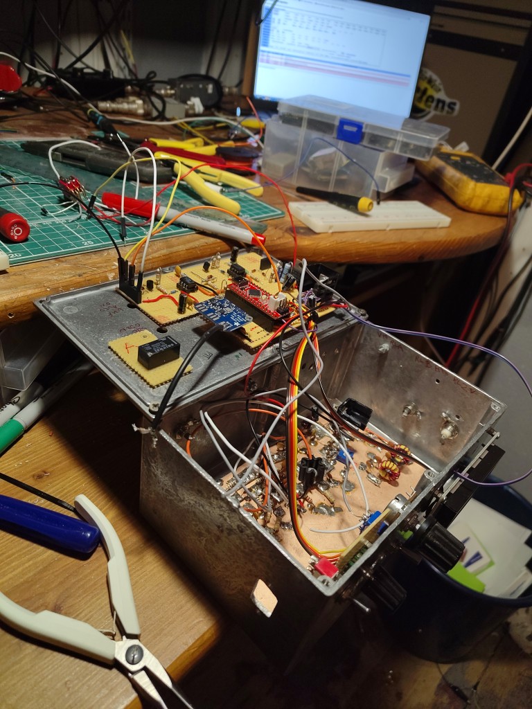
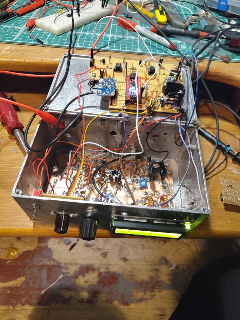
And here it is, finished and incorporated into the shack
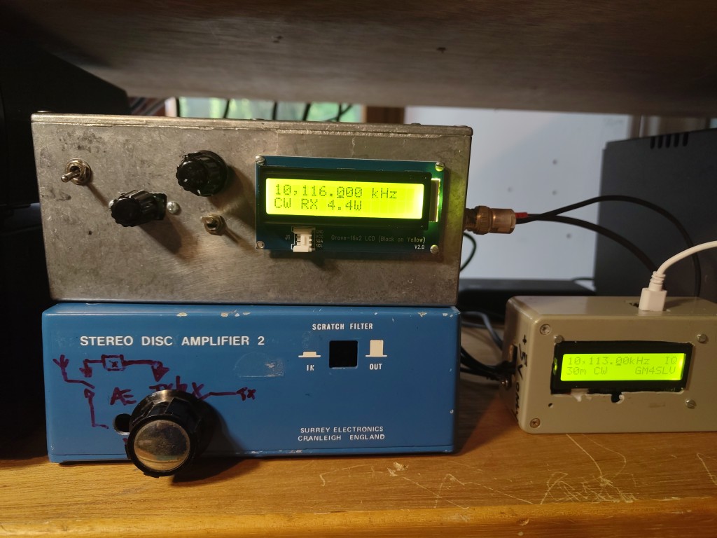
The final feature set:
-
Arduino (Seeeduino nano) controlling an SI5351 clock board
-
LCD Display
- Frequency
- RX / TX status
- Approximate TX Power setting (calculated from PA supply Voltage measured by the Arduino ADC)
-
Semi-QSK
- Internal Antenna C/O relay
- RX Mute line (ground to mute)
-
Variable TX Output power via voltage regulator on DC supply to final class-C IRF510 MOSFET
- Output adjustable 0.1W -> 5W
Separate TX and RX
I considered making a transceiver by putting the phasing RX [[..:radio:topics:arduino:30m_phasing_rx|]] and this TX together in one box, with a single Arduino / SI5351 but I decided to keep them totally separate. This harks back to an earlier time when this was a common way of operating. There is much more versatility from this approach.
Arduino Sketch
#include <rgb_lcd.h>
#include <si5351.h>

static const long bandStart = 10100000;          // start of VFO range
static const long bandEnd =   10150000;          // end of VFO range
static const long bandInit =  10120000;          // where to initially set the frequency
volatile long freq = 10116000;                   // the current freq
volatile long oldfreq = 0;                      // the previous freq
volatile long radix = 1000;                     // How much to change the frequency by, clicking the Up Down switches
volatile long oldradix = 0;                     // the previous radix
volatile int TX = 0;                            // 0=RX, 1=TX
volatile int oldTX = 1;                         // the old TX
unsigned int encoderA, encoderB, encoderC = 1;  // rotary encoder variables

int PAVoltPin = A0;
int PAVolt = 0;
int oldPAVolt = 0;

// Rotary encoder pins and other inputs
static const int rotAPin = 4;
static const int rotBPin = 3;
static const int radixPin = 2;
static const int PTTPin = 5;

int digit1 = 0;
int digit2 = 0;
int digit3 = 0;
int digit4 = 0;
int digit5 = 0;
int digit6 = 0;
int digit7 = 0;
int digit8 = 0;

double TXPower = 0.0;


float  Yint = 1.74E-6;
float   Slope = 2.18;

// Instantiate the Objects
rgb_lcd lcd;              // 3F the address of the LCD
Si5351 si5351;


void setup()
{
  // Set up I/O pins
  pinMode(rotAPin, INPUT);
  digitalWrite(rotAPin, HIGH);                    // internal pull-up enabled
  pinMode(rotBPin, INPUT);
  digitalWrite(rotBPin, HIGH);                    // internal pull-up enabled
  pinMode(radixPin, INPUT);
  digitalWrite(radixPin, HIGH);                   // internal pull-up enabled
  pinMode(PTTPin, INPUT_PULLUP);
  //digitalWrite(PTTPin, HIGH);                      // internal pull-up disabled
  pinMode(13, OUTPUT);
  analogReference( INTERNAL );

  // Initialize the display
  lcd.begin(16, 2);
//  lcd.backlight();
  lcd.noCursor();

  // Initialize the DDS
  si5351.init(SI5351_CRYSTAL_LOAD_8PF, 0, -32500);         // 62100 is the specific calibration factor for this Si5351 board
  si5351.drive_strength(SI5351_CLK0, SI5351_DRIVE_4MA);   // 2 mA for HB mixers


}


void loop()
{
  CheckEncoder();
  CheckRadixSwitch();
  CheckPTTPin();
  CheckPAVolts();
}

void CheckPAVolts()
{

PAVolt = analogRead(PAVoltPin);

if ( TX == 1 )
  {
    PAVolt = PAVolt / 0.92;
  }

if ( abs(PAVolt/10 - oldPAVolt) > 1 )
{


  TXPower = Yint * pow(PAVolt,Slope);
  UpdateDisplay();
  oldPAVolt = PAVolt/10;

}

//  lcd.print(PAVolt,0);
 // lcd.noCursor();

}
void CheckEncoder()
{
  byte encoderA = digitalRead(rotAPin);
  byte encoderB = digitalRead(rotBPin);

  if ((encoderA == HIGH) && (encoderC == LOW))
  {
    if (encoderB == HIGH)
      // Decrease frequency
      freq = constrain(freq - radix, bandStart, bandEnd);
    else
      // Increase frequency
      freq = constrain(freq + radix, bandStart, bandEnd);
  }
  encoderC = encoderA;

  if (freq != oldfreq)
  {
    UpdateDisplay();
    SendFrequency();
    oldfreq = freq;
  }
}

void CheckRadixSwitch()
{
  if (digitalRead(radixPin) == 0)
  {
    radix = radix / 10;
    if (radix < 10)
      radix = 10000;
    delay(200);
  }

  if (radix != oldradix)
  {
    UpdateDisplay();
    oldradix = radix;
  }
}


void CheckPTTPin()
{
  if (digitalRead(PTTPin) == 0)
  {
    TX = 1;
    digitalWrite(13, HIGH);
  }

  if (digitalRead(PTTPin) == 1)
   {
    TX = 0;
    digitalWrite(13, LOW);
   }

  if (TX != oldTX)
  {
    UpdateDisplay();

    SendFrequency();
    oldTX = TX;
  }
}

void UpdateDisplay()
{
  // freq

    digit1 = (freq%10);
    digit2 = ((freq/10)%10);
    digit3 = ((freq/100)%10);
    digit4 = ((freq/1000)%10);
    digit5 = ((freq/10000)%10);
    digit6 = ((freq/100000)%10);
    digit7 = ((freq/1000000)%10);
    digit8 = ((freq/10000000)%10);


  lcd.setCursor(0,0);
  lcd.print(digit8);

  lcd.setCursor(1,0);
  lcd.print(digit7);

  lcd.setCursor(2,0);
  lcd.print(",");

  lcd.setCursor(3,0);
  lcd.print(digit6);

  lcd.setCursor(4,0);
  lcd.print(digit5);

  lcd.setCursor(5,0);
  lcd.print(digit4);

  lcd.setCursor(6,0);
  lcd.print(".");

  lcd.setCursor(7,0);
  lcd.print(digit3);

  lcd.setCursor(8,0);
  lcd.print(digit2);

//  lcd.setCursor(9,0);
//  lcd.print(digit1);

  lcd.setCursor(10,0);
  lcd.print("kHz");

 // lcd.print(freq);
  // mode
  lcd.setCursor(0, 1);
  lcd.print("CW TX ");
 // lcd.setCursor(10, 1);
  // PTT

  lcd.print(TXPower,1);
  lcd.print("W");
  lcd.setCursor(11, 1);
  if (TX == 1)
    lcd.print("[TX]");
  if (TX == 0)
    lcd.print("[RX]");
  if (radix == 10000)
  lcd.setCursor(4,0);
  if (radix == 1000)
  lcd.setCursor(5, 0);
  if (radix == 100)
  lcd.setCursor(7, 0);
  if (radix == 10)
  lcd.setCursor(8,0);
//  if (radix == 1)
//  lcd.setCursor(9,0);
  lcd.cursor();
}


void SendFrequency()
{
    if (TX == 1)
    {
      si5351.set_freq((( freq) * 100ULL), SI5351_CLK0);
      si5351.output_enable(SI5351_CLK0, 1);
    }
    else
    {
       si5351.output_enable(SI5351_CLK0, 0);
    }
}